
The Hardware Stack
Scaling metal 3D printing from tabletop prototypes to public monuments requires a fundamental departure from Laser Powder Bed Fusion (LPBF). While LPBF offers extreme precision, its build volumes are suffocatingly small for large-scale art. Most practitioners in Berlin and Sao Paulo have shifted toward Wire Arc Additive Manufacturing (WAAM) or Directed Energy Deposition (DED). These systems utilize an electric arc or laser to melt metal wire or powder in real-time, allowing for deposition rates that can exceed 5kg per hour. The trade-off is a coarser finish and a massive increase in thermal energy, which complicates the structural integrity of every joint.
The physics of large-scale deposition introduce a variable that small prints ignore: gravity-induced deformation. As the bead of molten 316L stainless steel or Ti6Al4V is laid down, the weight of the overlying layers exerts pressure on the lower, still-cooling sections. This creates a compressive force that can warp the geometry before the print is even finished. When you integrate a load-bearing joint, you are not just designing for the final weight of the sculpture, but for the dynamic weight of the molten metal during the build process. Failure to account for this leads to the dreaded structural slump.
Why do so many large-scale prints fail at the seams? The answer lies in the mismatch between the deposition rate and the cooling rate. In a WAAM system, the heat input is immense, and the thermal gradient between the molten pool and the cold substrate is steep. This gradient creates residual stresses that act like invisible springs, pulling the joint apart from the inside. If the joint is a simple butt-weld, these stresses concentrate at the interface, leading to immediate cracking or long-term fatigue failure.
Precision in this context is not about microns, but about thermal management. A sculpture standing five meters tall in an outdoor plaza in Osaka must withstand wind loads and thermal expansion. The joint is the point of maximum vulnerability. To solve this, the artist must stop thinking like a sculptor and start thinking like a bridge engineer. The joint is no longer a connection; it is a calculated distribution of force.
Prerequisites for Structural Stability
- WAAM or DED hardware capable of multi-axis movement (5-axis or robotic arm).
- Finite Element Analysis (FEA) software such as Ansys or Abaqus for stress simulation.
- Industrial-grade 316L Stainless Steel or Ti6Al4V wire/powder.
- Post-processing equipment: CNC milling for joint mating surfaces and TIG welding for reinforcement.
- Non-Destructive Testing (NDT) tools, specifically ultrasonic or X-ray scanners for internal porosity checks.
Before a single bead of metal is deposited, a rigorous simulation phase is mandatory. FEA software allows the practitioner to visualize the stress concentrations within the joint under various load scenarios. For a large-scale piece, you must simulate not only the final static load but the transient thermal loads during the print. This reveals where the metal will likely warp and where the joint will be most prone to failure. Relying on intuition in additive manufacturing is a recipe for a catastrophic collapse.
Executing the Load-Bearing Joint
- Perform Topology Optimization: Use software to remove material from non-load-bearing areas and reinforce the joint's primary stress paths.
- Design the Interface Geometry: Replace simple flat joints with interlocking dovetails or sinusoidal interfaces to increase surface area and mechanical grip.
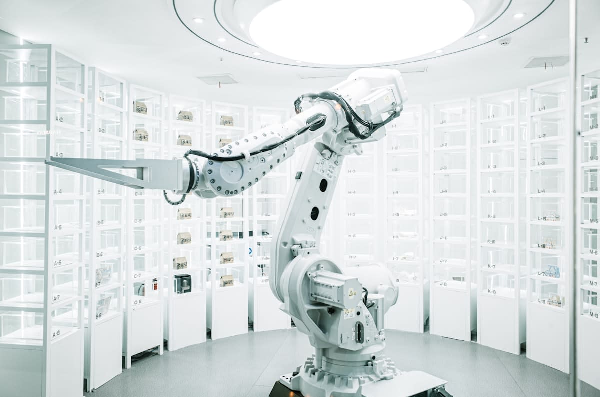
- Calculate the Thermal Deposition Path: Program the robot to alternate deposition zones to avoid heat accumulation in a single area of the joint.
- Integrate Hybrid Reinforcements: Design the print to accept internally inserted forged steel rods or plates at critical load points.
- Execute Controlled Cooling: Implement a gradual temperature ramp-down or use a heated build plate to minimize residual stress.
- Perform Post-Print Machining: CNC mill the joint surfaces to a tolerance of +/- 0.1mm for a perfect fit if the joint is modular.
Topology optimization is the first line of defense. Instead of a solid block of metal, the joint should follow the natural flow of the load. By using generative design, you can create an organic, bone-like structure that is lighter yet stronger than a traditional beam. This reduces the total mass of the print, which in turn reduces the gravitational stress on the lower layers. In a 316L stainless steel print with a yield strength of approximately 290 MPa, optimizing the geometry can increase the load capacity by 40% while reducing material use by 30%.
Interlocking geometry is where the real structural gain occurs. A flat joint relies entirely on the fusion of the metal, which is vulnerable to porosity. A sinusoidal or dovetail joint, however, introduces mechanical interlocking. This means the joint cannot fail unless the metal itself shears. By increasing the contact surface area, you distribute the load across a wider region, effectively lowering the stress per square millimeter. This is a critical requirement for any piece intended for public installation.
The deposition path is the most overlooked variable in joint integrity. If the robot deposits metal in a continuous spiral around the joint, it creates a concentrated heat zone that can lead to localized grain growth. Large grains are generally weaker and more prone to cracking. To counter this, use a 'staggered' or 'checkerboard' deposition strategy. By moving the heat source across different quadrants of the joint, you allow each section to cool slightly before the next layer is added, resulting in a more refined and isotropic microstructure.
Hybrid manufacturing is the secret of the world's most stable metal prints. Purely additive joints are rarely sufficient for extreme scales. The most resilient approach involves designing a cavity within the 3D printed joint to house a forged steel core. This core acts as the primary load-bearer, while the 3D printed metal provides the form and secondary support. This combination leverages the precision of additive manufacturing and the raw strength of forged steel, ensuring the sculpture can withstand seismic activity or high wind speeds.
Thermal Stress and the Heat-Affected Zone
The Heat-Affected Zone (HAZ) is the region of the base metal that did not melt but had its microstructure altered by the heat of the deposition. In large-scale WAAM, the HAZ can be several millimeters wide. This zone often becomes the weakest point of the joint because the thermal cycling causes precipitation of carbides or other phases that embrittle the metal. If the joint is designed without considering the HAZ, the sculpture will not fail in the middle of a printed layer, but exactly at the boundary where the heat peaked.
| Joint Type | Load Capacity | Print Complexity | Primary Failure Mode |
|---|---|---|---|
| Fusion Joint | High | Low | Thermal Cracking |
| Interlocking Joint | Medium-High | High | Shear Stress |
| Hybrid (Core-Inserted) | Extreme | Medium | Interface Corrosion |
| Mechanical Fastener | High | Low | Fastener Fatigue |
To mitigate HAZ embrittlement, controlled cooling is non-negotiable. Rapid quenching can lead to martensitic transformations in certain alloys, making the joint brittle. Conversely, too slow a cooling rate can lead to excessive grain growth. The ideal is a managed ramp-down, often achieved by enclosing the build in a temperature-controlled chamber or using induction heating to keep the substrate at a constant 200-400 degrees Celsius. This reduces the thermal gradient and prevents the internal 'spring' effect of residual stress.
The Porosity Trap
Never assume a print is stable just because it looks solid. Internal porosity in WAAM prints can reach 1-3% if parameters are off. A single void in a load-bearing joint can act as a stress riser, triggering a crack that propagates through the entire structure.
Validation and Failure Analysis
Once the print is complete, the validation phase begins. Visual inspection is useless for internal joints. Ultrasonic testing (UT) is the industry standard here, sending high-frequency sound waves through the metal to detect voids or lack of fusion at the joint interface. In a high-stakes installation in Houston or Tokyo, an X-ray scan of the primary load-bearing joints is often required by city engineers to certify the piece for public safety. If a void larger than 2mm is found in a critical area, the joint must be excavated and re-welded.
The final step is the physical load test. This involves applying a calculated percentage of the expected maximum load to the sculpture using hydraulic jacks and monitoring the deflection with dial indicators. If the joint deflects more than the predicted FEA value, it indicates a lack of stiffness, likely due to internal porosity or poor fusion. This is the moment of truth where the theoretical model meets the reality of the material.
Common Pitfalls
The most frequent error is the Magic Wand Fallacy: the belief that the 3D printer handles all structural concerns automatically. Software can suggest a shape, but it cannot account for the chemistry of a specific batch of wire or the humidity of the studio. Many artists fail because they skip the post-print stress-relief annealing process. Heating the entire sculpture to a specific temperature and cooling it slowly is the only way to truly neutralize the residual stresses locked into the joints.
Another critical mistake is over-engineering the joint to the point of adding excessive mass. Adding more metal to a joint often increases the thermal load during the print, which paradoxically increases the risk of warping and cracking. The goal is not maximum mass, but maximum efficiency. A lean, topology-optimized joint with a forged core will always outperform a massive, purely additive block of metal.